
Hard Disk Firmware Hacking (Part 5)
“Discovery requires experimentation”
This weekend I made a pretty big breakthrough which lead to me making a few smaller breakthroughs and ultimately negating most of my previous research. I’ve also learned that “not reinventing the wheel” isn’t always the best option, especially when it comes to trusting other people’s research.
One of the main goals was to find a way to quickly and easily reprogram the hard disk, given physical access. In the spritesmods post he had remove the flash chip from the PCB and attached it to some veroboard, so he could swap it between the hard disk and the flash programmer. Obviously it’s not very practical for me to have to keep disconnecting and reconnecting the flash chip, and especially impractical for an adversary looking to quickly infect a disk.
As most already know, it is possible to flash WD hard disk firmware from within the OS as long as the account has Admin/Root privileges. The disk must be running in order to accept SATA commands and must be restarted to load the new firmware. If the new firmware has errors the disk cannot start, therefore the firmware cannot be fixed (this is known as bricking). Due to the fact I’m hacking about with the firmware I’m likely to brick the device, so i needed another way of flashing it.
In-Circuit Programming
In circuit Programming (ICP) is the ability to program a flash chip or other component, while it’s still connected to the circuit. In the last article I was able to find the test ports that connected to the flash chip, but was unable to program it, however; after some experimentation over the weekend I finally managed to achieve ICP.
The Problem One of the biggest problems with ICP is that in order to write the flash chip you need to power it, but because it’s connected to the rest of the circuit you end up powering other chips, which send data on various buses and interfere with your attempts to talk to the flash.
To prevent interference on the SPI bus, it’s usually enough to hold down the reset button or short the reset signal to ground, resulting in the system being held in reset and unable to start (giving you uninterrupted access to the flash’s bus).
Here’s a list of what I’d tried.
- Powering the flash directly with 3.3v supply
- Powering the flash directly with 3.3v supply while holding the system in reset
- Powering the entire system by plugging in the HD
- Powering the entire system by plugging in the HD while holding the system in reset
I was ready to give up as nothing was clearly working (my SPI programmer couldn’t so much as detect the flash chip), but on Saturday I decided to have one last go, and it worked straight away (sort of).
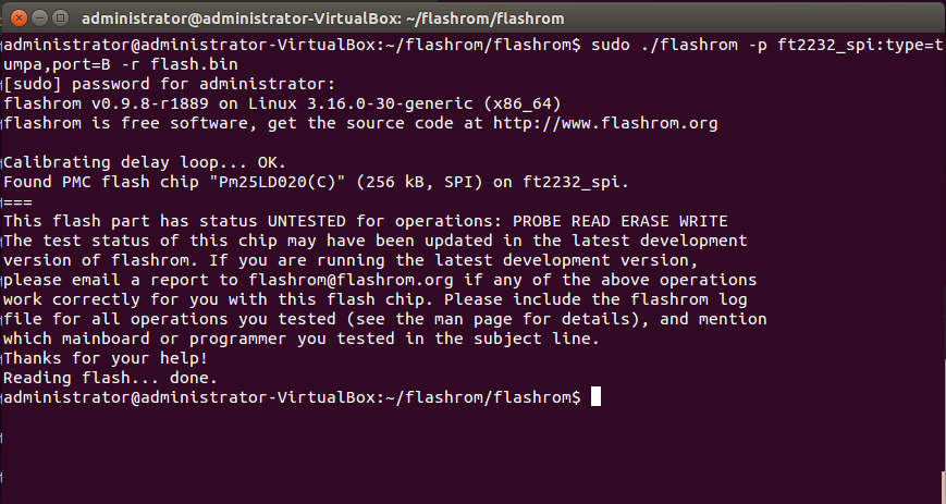
The SPI programmer was able to detect the flash chip, but most of the data being read was erroneous. On investigation I found that the VCC (power) wire had come unstuck from the test point and was now hanging off the desk. So if the VCC wire wasn’t connected and the system wasn’t plugged in, how was it reading the flash chip?
After more experimentation I found that the circuit was set up in such a way that some of the voltage being sent to the MISO pin (about 1.2v of it) was somehow feeding back onto the VCC rail and powering the chip….wat. As I’ve said I’m not an electronics expert, and this had me completely baffled, but it also showed me that reading the chip in circuit was possible, i just needed to learn its secrets.
The Solution After extensively more experimentation with a side order of experimentation and failure, I found that holding the system in reset (the solution to most ICP problems) was actually the only issue. I had been leaving the JTAG connected to the system and it was pulling the reset pin low (holding it in reset), so when I wasn’t holding the system in reset the JTAG was. After disconnecting the SRST (reset) pin of the JTAG, everything worked perfectly as long as the disk wasn’t plugged in and I powered the flash chip directly. It seems that this system is designed for ICP to be done without holding it in reset and doing so causes issues.
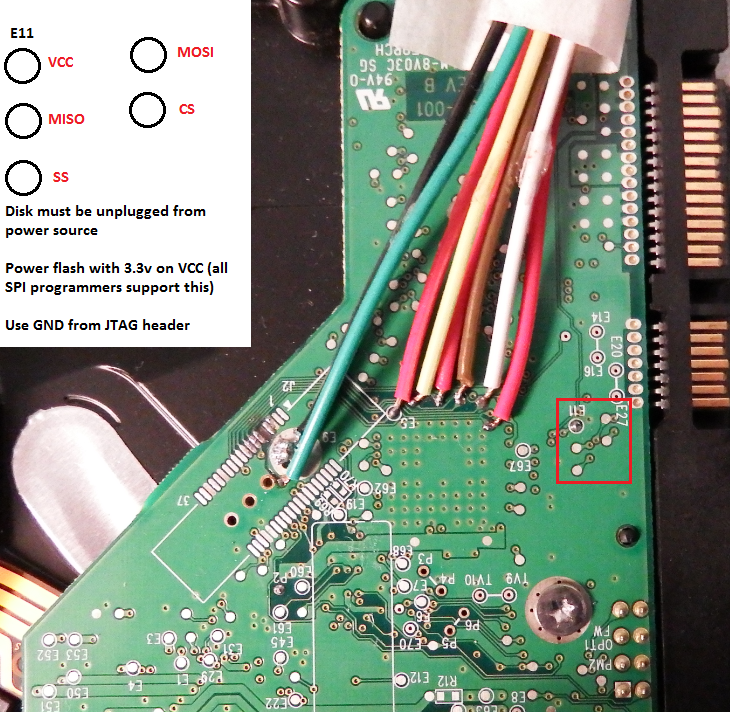
Here is the updated image from the last article.
If you have a USB device which allows for SPI programming and is supported by “flashrom”, like I do. You can connect it to the computer and use flashrom to read, write, and erase the flash. The TUMPA is an especially nice board because it has 2 channels, so you don’t have to disconnect the JTAG to use SPI.
Don’t reinvent the wheel they said, It’s a waste of time they said
Before i started hacking I’d decided to read other people’s research to get a good idea of where to start. Resourceful, right? Well it actually turns out that most of the research I’ve based mine on was either wrong or just doesn’t apply to this hard disk.
I was under the impression that when connecting the JTAG and issuing a “reset halt” command, the system would be halted before any code was run, and I could step through the bootstrap while it read the bootloader from flash and execute it, this wasn’t the case.
After playing around by writing my own code to the flash, i realized that it’s is being read into memory and executed long before the system is halted. In fact it seems like the code at 0xFFFF0000 is just some kind of debug console which is only jumped to if a halt command is issued, or the reading / executing the code from flash fails. By the time the JTAG is able to connect and issue a command, the entire kernel has already been loaded and initialized, which explains why I couldn’t set any breakpoints on the bootloader.
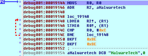
I can write a breakpoint to the flash so that an exception is generated and the system fails to load, then remove the breakpoint and manually jump back to the bootloader, but for whatever reason the system doesn’t boot properly the second time. This isn’t a huge issue because I can still debug the bootloader up until the a certain point (as long as any code I write is run during early boot, I can debug that too), but until I can find why it fails the second time, there is a window of time between the late boot stage and early kernel initialization where I can’t debug.
Success
My main goal was to inject code into the firmware both by running an executable on the target computer and with physical access to the hard drive, which I’ve achieved. Now I’ll just poke around and see what I can do with it.
If you’re wondering how easy it would be for an attacker to infect a hard drive’s firmware, here are two quick ways they could to do it.
- Sending firmware update commands over the SATA interface from the host computer (requires root/admin).
- Create a portable SPI programmer that can flash the firmware by being pressed against the test points on the bottom of the hard drive (would only take about 5 seconds).
Something…something…aliens…something…something…government… *puts on tinfoil hat*
Part 6 (Final part): https://www.malwaretech.com/2015/05/hard-disk-firmware-hacking-final-part.html


